LAB 1A - Artemis Setup
Introduction:
The aim of this lab to set up Sparkfun Artemis board, which is going to be used for the rest of the semester and be the crucial aspect of communication between robots.
Prelab 1A: Installation of Arduino IDE
The first step of the Prelab 1A was to install the latest versions of Arduino IDE (version 2.3.4) and Sparkfun Apollo3 boards manager. Furthermore, I was able to successfully install all the required libraries for the prelab and thus perform the proposed tasks below.
Lab 1A:
Task 1: Blink
The example Blink code was run in order to confirm that we are able to program simple code onto the Artemis board.
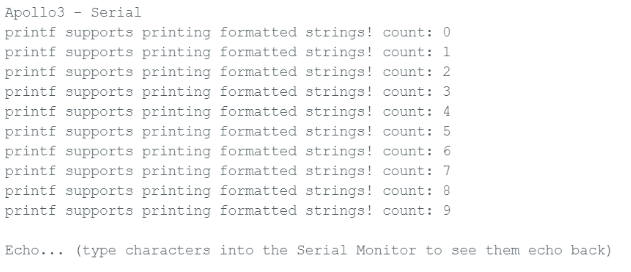
Task 2: Serial
This task was implemented in order to test for the UART communication between the computer and the board. Considering that I experienced issues with my Serial Monitor due to which my laptop restarted, I set the baud rate to 9600 instead of 115200 which was successful.
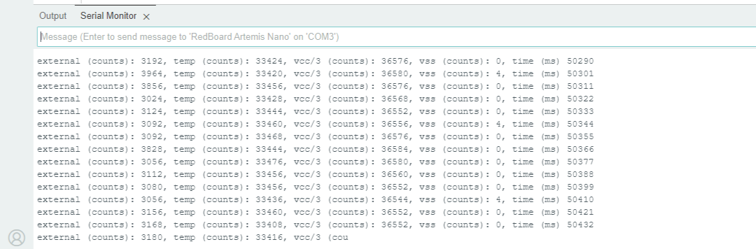
Task 3: Analog Read
This task was performed by utilizing the analog-to-digital converter (ADC), which is an integrated device which converts analog voltage to a digital signal. AnalogRead() function thus enables reading out the temperature data from the sensor. The temperature recorded was about 33400 counts, however, once the chip was held, the temperature would slightly increase. Therefore, the temperature sensor was able to successfully detect the changes.
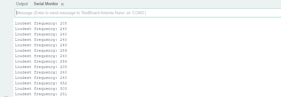
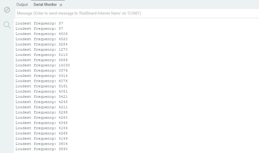
Task 4: Microphone Output
This task taught us how to use the microphone integrated onto the Artemis board. This is performed through using the PDM or pulse-density-modulation code provided. The first image demonstrates the frequency while there was no to little sound detected. However, the second image demonstrates the frequencies captured while talking. Hence, the microphone sensor was able to distingues between loud and quiet sounds successfully.
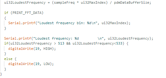
Additional task for 5000-level students: "C" note detector
This task taught us how to program a "C" note detector by manipulating on-board LED switching into the Microphone_Output code. The way I implemented the task is by detecting the frequency that is 523 HZ +/- 10 Hz to introduce some error, and in case the freqency detected is in-between the desired range for not "C5", then the LED turns on (blue light) as can be seen in the recorded video. For other frequencies, the LED turns off.
Discussion:
The performed tasks were very insightful and helpful in teaching us how to navigate the Arduino IDE environment, and with the "C" speaker assignment, practice playing with the provided code to create new functionalities.
LAB 1B - Bluetooth Communication
Introduction:
This section of the lab focuses on establishing a Bluetooth connection between the Artemis board and the computer. The environments used for this part of the lab were Arduino IDE and Jupyter Lab in order for the bluetooth connection to be established.
Prelab 1B: Installation of Python and Virtual Environment
Before implementing Bluetooth communication, the necessary libraries were installed, including ArduinoBLE (Bluetooth Low Energy, which refers to circumstances of Bluetooth optimization that do not need large data transfers). These libraries allow the Artemis board to act as a BLE peripheral, enabling it to send and receive data wirelessly.
The newest version of Python - Python 3.13 - as well as pip were installed. The versions were verified by the commands:
python3 --version Afterwards, we may set up the Jupyter Lab environment for the computer interface, which is enabled through the following code snippet:
 python3 -m pip install --user virtualenv
 python3 -m venv FastRobots_ble
Furthermore, virtual environment ought to be activated in order for Jupyter Notebooks to be used:
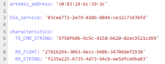
.\FastRobots_ble\Scripts\activate Another significant aspect of the Prelab 1B was the installation of ArduinoBLE, which thus enabled loading and burning of ble_arduino.ino. My device's MAC address was thus printed out on the Serial Monitor, after which connections.yaml file in Jupyter Lab was edited to reflect the MAC address.
Lab 1B: Tasks
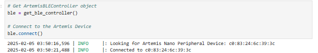
Throughout these lab 1B tasks, I had to connect to the Artemis Device in Jupyter Notebook whenever the Bluetooth connection ought to be established.
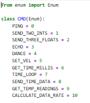
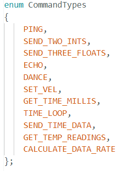
Furtermore, with every case initiation, we update enums in both ble_arduino.ino on the Arduino side, and cmd_types.py on the Jupyter Notebook side.
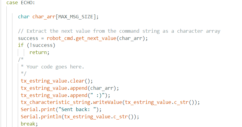
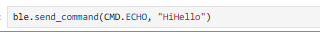
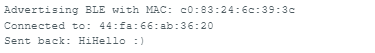
Task 1: ECHO
The first task aimed to send an echo command that holds a string to the Artemis board, and afterwards receive the augmented version of the string back to the computer, testing the mutual communication. Below are snippets of Arduino IDE code and Jupyter Notebook code, and the Serial Monitor Output, in order.
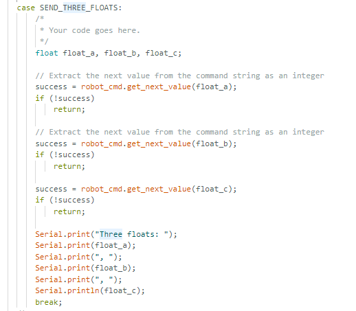
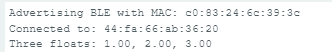
Task 2: Send_THREE_FLOATS
Similarly to the previous task, in this task we send three floats instead. Arduino IDE code, Jupyter Notebook code, and the Serial Monitor output are in order.

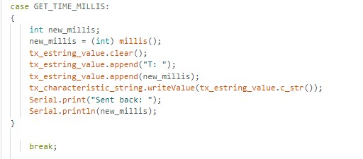
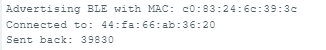
Task 3: GET_TIME_MILLIS
This task asks for the Artemis to reply with a string representing current time. Arduino IDE code, Jupyter Notebook code, and the Serial Monitor output are in order. It can be seen that the Python code sends the GET_TIME_MILLIS command and receives a string representing the current time. The time is thus also reflected on the Serial Monitor.
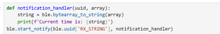
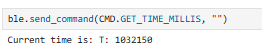
Task 4: Notification Handler
The notification handler integrates ble.start_notify() function, which calls the handler whenever a message is received from the Artemis board. The received string is printed out. Arduino IDE code, Jupyter Notebook code, and the Serial Monitor output are in order. It can be seen that the Python code sends the GET_TIME_MILLIS command and receives a string representing the current time. The time is thus also reflected on the Serial Monitor.
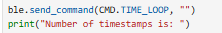
Task 5: Looped version of GET_TIME_MILLIS
The loop function named TIME_LOOP is created in order to consistently run GET_TIME_MILLIS and determine how fast the data is sent. Arduino IDE code, Jupyter Notebook code and output, and the Serial Monitor output are in order.
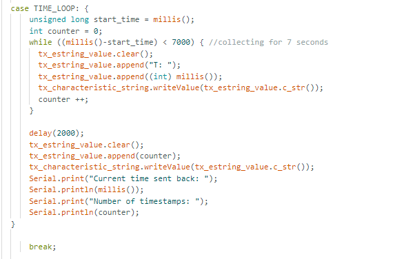
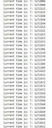

The looped function sent exactly 406 samples in 6.93 seconds, hence averaging at about 58.6 messages/s.
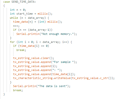
Task 6: SEND_TIME_DATA
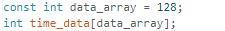
This function stores timestamps in an array of 128, looping through the array and thus sending the entries fast. As opposed to the previous function TIME_LOOP, as in this case we gather the data and then send it in different loops. Arduino IDE code, Jupyter Notebook code and output are in order. Two new global variables of time_data representing an array and data_array are instantiated.
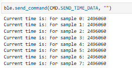
Therefore, 128 time stamps were sent ranging from 2496060 ms to 2496064 ms. This method enhances frequency of the time stamps due to the fact that messages do not have to wait for the time stamps in between.
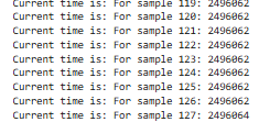
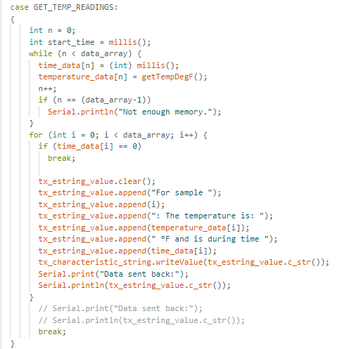
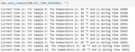
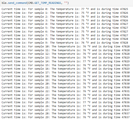
Task 7: GET_TEMP_READINGS
This task is very similar to the previous task, except that now we are incorporating temperature values as well with the time stamps. Arduino IDE code, Jupyter Notebook code and output are in order. A new global variable of temperature_data representing an array is instantiated.

Task 8: Advantages and disadvantages between the methods
From what can be observed, the first method, that is the method of the TIME_LOOP function, cannot send data as fast as SEND_TIME_DATA, due to the fact that it can be observed it has a bigger difference in-between consecutive timestamps. This method can send about 60 messages/s as calculated. Hence, even though it may not be able to send high-resolution data as well, it is the preferred method in the cases where we want the data to be transferred in the exact moment, yet we do not mind for the quality of it as much. This is due to the fact that TIME_LOOP can consistently send the last sample as the most recent sample of the data.
On the other hand, the second method utilized by SEND_TIME_DATA as well as GET_TEMP_READINGS is much better at sending high resolution data, and can send thousands of samples/s. However, unlike TIME_LOOP, this methodology cannot be used for most recent, or real-time data sending, as it distributes and collects data into different loops. Furthermore, those arrays and loops instantiated can take up a lot of memory. Considering that Artemis board has 384 kB of RAM, and a float uses 4 bytes of RAM, then we have in total of 96 000 data points available. If we sample 16-bit values at 150 Hz every 5 seconds, we would use 1500 bytes. Hence, 384 kB/1500 bytes would be equal to about 256 5-second intervals of data that are available in the memory.*
Additional tasks for 5000-level students
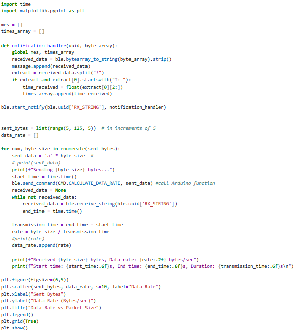
Effective Data Rate and Overhead
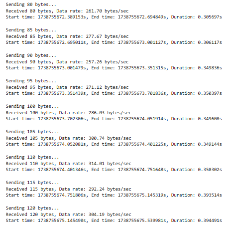
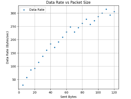
My idea behind this was to send a message from the computer and then receive a reply from the Artemis. The sent_bytes were incremented in increments of 5 from 0 to 120. The first screenshot represents the Jupyter Notebook code, after which we can see a screenshot representing the packets being sent (from 80 bytes to 120 bytes in this screenshot example) with their data rate displayed, as well as the duration of transmission. Lastly, a graph can be seen, showing the data rate versus the packet size. From the graph, it can be inferred that the curve is almost linear with a few outliers, where with the increase of the bytes sent to the Artemis, we have an increase in the data rate as well as the duration of transmission.
Short packets cause overhead because the transmission has a fixed size, and thus with sending 5-byte packets we have a lower effective data rate. On the other hand, larger packets definitely do improve the efficiency because there is a higher effective data rate and the transmission is more efficient as the overhead is spread out more across the actual data.
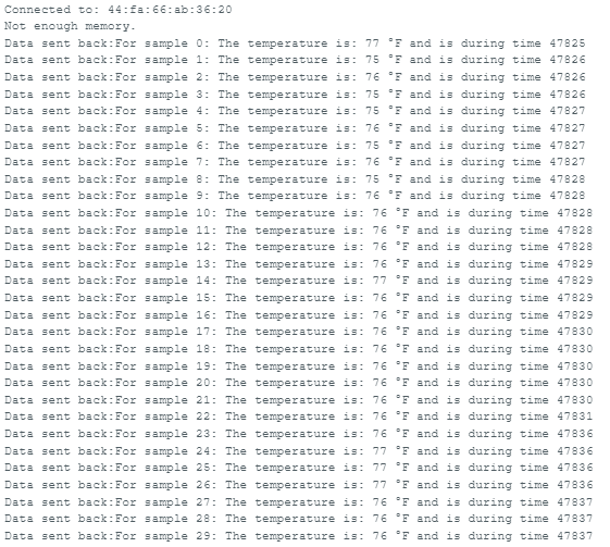
Reliability
Reliability was tested through sending data at higher rate. Furthermore, I compared the outputs of Arduino IDE Serial Monitor's output with the Jupyter Lab's output to verify the reliability. As can be inferred from the two screenshots, the Jupyter Notebook and the Serial Monitor outputs match completely, hence there is high reliability even when sending higher rate from robot to computer. In extreme cases where data is sent very quickly, there might be a loss in packets as the computer would not be able to process the data quickly. However, that was not detected in this case.
Discussion:
Lab 1 provided me with a hands-on experience in working with Bluetooth Low Energy (BLE) and understanding its significance for wireless communication. The lab was important for setting up Artemis for future lab projects.
*The equation was learned from Mikayla Lahr's Lab 1 Page (Spring 2024).