LAB 4 - Motors and Open Loop Control
Introduction
The aim of this lab was to navigate the car through implementing open loop control, instead of navigating it with the provided controller. It was implemented through integrating two dual motor drivers which navigate the car conrol, and are connected to the car motors and the Artemis board.
Prelab 4
The prelab involved developing a plan to integrate the motor drivers, along with the sensors integrated in the previous two labs. Furthermore, the provided a reading about using the oscilloscope as well.
Implementation diagram
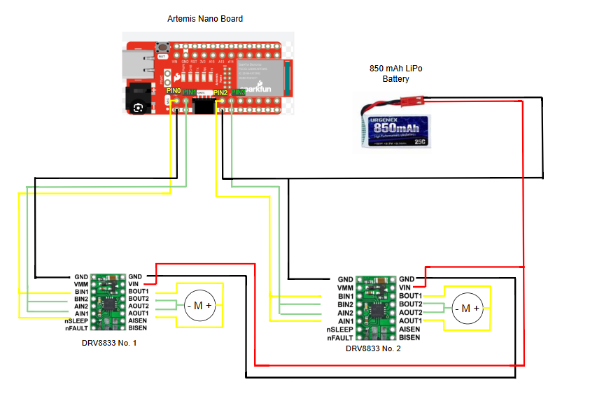
This lab required us to implement two DRV8833 motor drivers in order to control the car motors. Ultimately, the motor drivers ought to connect to the provided 850 mAh battery. From the proposed diagram below, it can be concluded that the used Artemis board analog pins which connect to the motor drivers in order to establish the PWM output are pins A0 to A3, as labeled.
The battery discussion
It ought to be noted that the motors as well as the motor drivers, are powered on the 850 mAh battery, compared to the rest of the hardware including the Artemis board, which are powered on a separate provided battery. This is due to the fact that the high-speed switching, as well as the considerable power can lead to EMI ripples in the power supply. Hence, in order to avoid such outcome as well as the interference with electronics which are delicate and fragile, the batteries are independent of each other.
Lab Tasks
Testing the Motor Drivers using the oscilloscope
As proposed by the lab manual, I initially soldered the pins of a single motor driver onto the Artemis analog pins shown in the implementation diagram above. Furthermore, the outputs of the motor drivers are thus probed using the oscilloscope for easier analysis, while the inputs of the motor driver represent the generated PWM signals. Furthermore, the VIN signal labeled on the diagram above, as well as the GND signal (which was also connected to the Artemis board) were connected to the power supply. The visualization of the setup is represented in the image below.
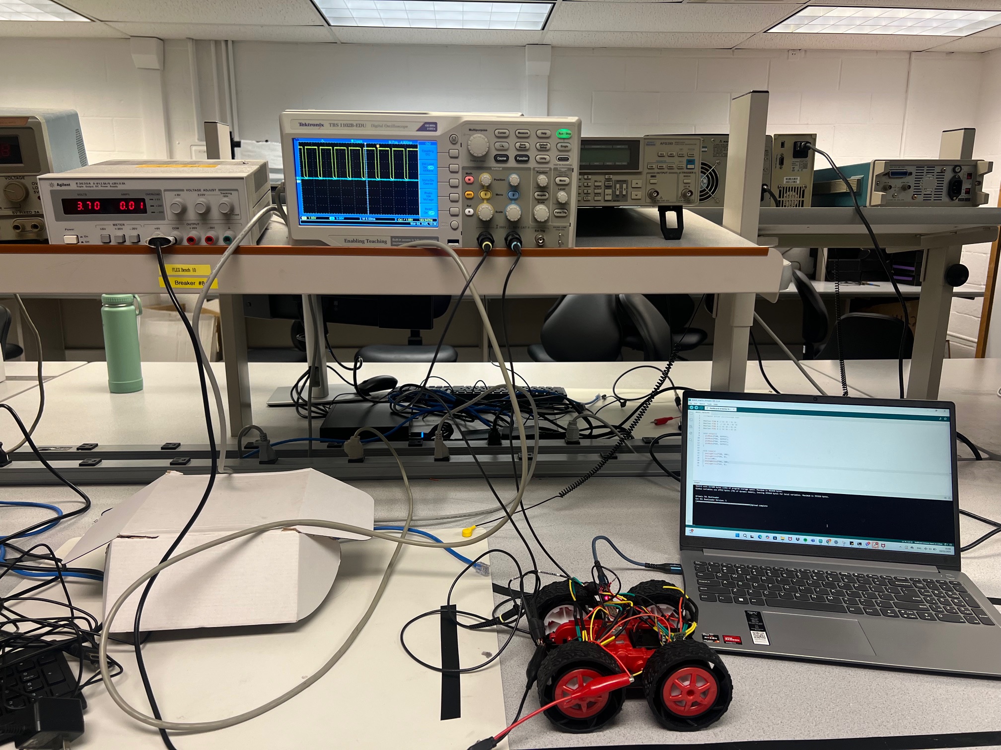
The attached image shows the battery supply's set voltage of 3.7 V, its probes on VIN and GND signals, as well as the oscilloscope reading of the motor driver's outputs. Analyzing the datasheet of the provided moto drivers, it is proposed that the notor voltage ought to be within the range of 2.7 V - 10.8 V. The voltage of the 850 mAh battery is 3.7 V, hence, the power supply was set to be of the same voltage to simulate the battery voltage used for the remaining parts of the lab.
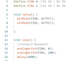
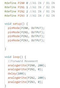
The implemented code for testing the motor drivers showcases the functionality of PWM by implementing the analogWrite() function, where PIN1 representing A2 IN and B2 IN is set to high (in this case 200), while PIN0 representing A1 IN and B2 IN is set to low, or 0.
The oscilloscope image is as the following:
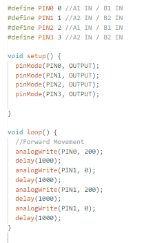
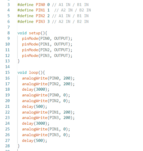
After verifying that a single motor driver showcases correct outputs on the oscilloscope, a similar methodology was followed to account for the second driver in the code post its soldering. In the proposed Arduino code below, pins PIN0 and PIN2 were individually set to the value of 200 in the analogWrite() function while other pins were set to the output of 0. As such, 4 different combinations of high and low values were tested on the 2 motor driver pins. Analyzing the oscilloscope readings, it can be inferred that it correctly illustrates the positive 3.7 V to the motors which are set by the power supply, and hence, maintains a constant voltage value.
Below is the code implemented for both the motor drivers testing on the oscilloscope.
Motor Driver Wheels
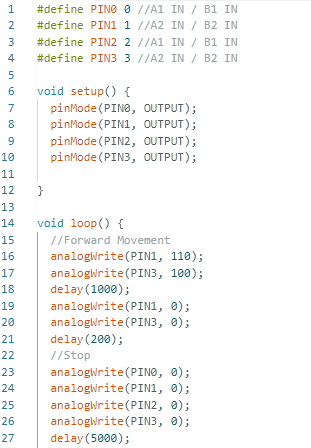
After the confirmation from the oscilloscope readings that our motor driver outputs behave as expected, the next step of the open loop control development is to connect our drivers to the provided wheels. For incremental purposes, I connected a single motor driver to one side of the wheels, and tested by using similar code to the one provided above. The video of the wheels spinning in both directions, alongside the complementary code, can be found below.
As can be analyzed, I incrementally tested the driver integration with one side of the wheels by getting the power through through the power supply, and battery, spinning in both directions. Afterwards, I tested both drivers with two sets of wheels, first with the power supply, and then with the battery, spinning in both directions.
Furthermore, this leads to the conclusion that the motor driver installation was successful and hence soldering the drivers to the aforementioned 850 mAh battery was now a possible step towards full circuitry integration.
Installation of all components
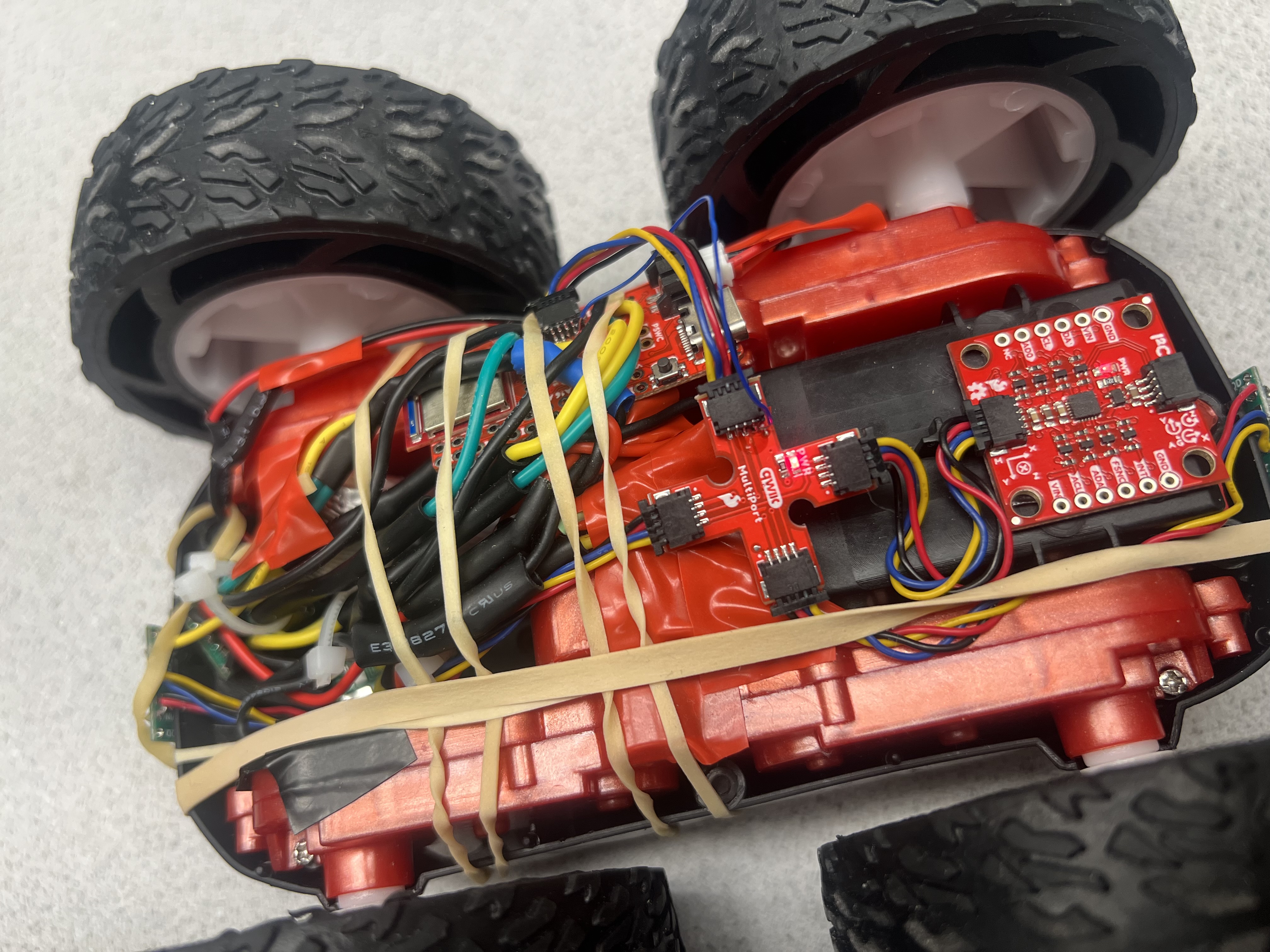
After the successful soldering and testing, the full integration of our electronics looks like the following on the labeled image:
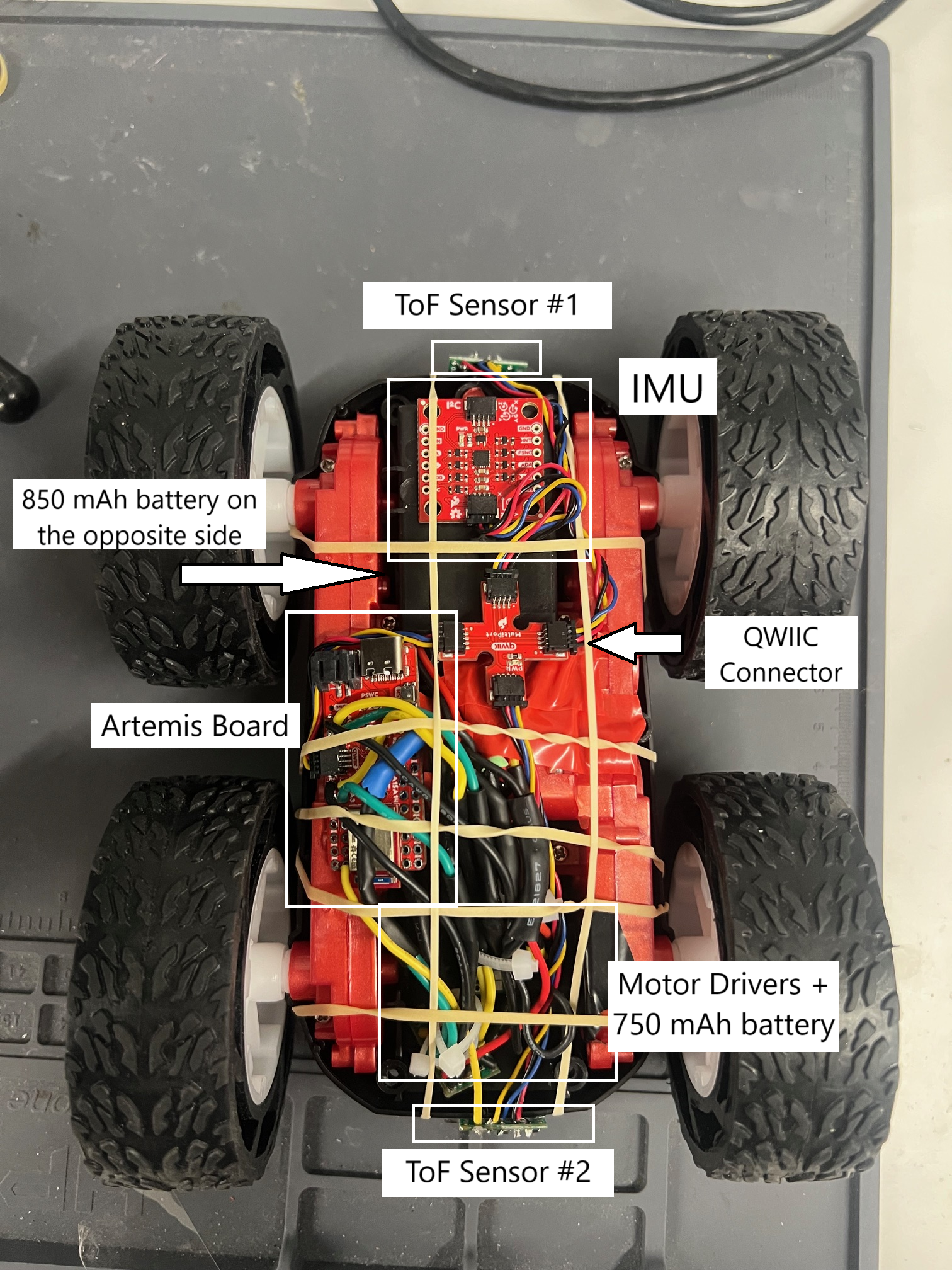
Compared to lab 3, I have implemented a few changes. I changed my motor drivers to be close together, so that I could secure the electronics better in a larger compartment, considering that they require the most wiring. What is more, the motor drivers are isolated from other electronics except the battery, so that EMI is not created. Furthermore, I spaced out my ToF sensors, where one is in the front, and one is in the back of the car for more accurate collection of sensor data. As per my discussion with TA Harry, I placed the IMU on the flat surface created by the 850 mAh battery compartment, so that I could have as accurate of position readings as possible.
Finally, the car is tested with a stop timer as follows with the complementary code:
Lower Limit PWM value discussion
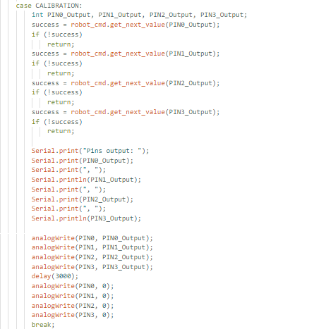
In order to experimentally explore the lowest value of PWM, I wrote Arduino code, which I sent over through Bluetooth. This allowed for me to manipulate the values of every individual drivers' output pins by running a ble.send_command() on the Python side. The implemented case CALIBRATION was adapted from case SEND_TWO_INTS from lab 1. Furthermore, analogWrite() statements were added to control the values of the output pins in Python.

Through experimentation with the values, it was determined that the lower limit in PWM value for which the robot is able to move forward for both of the wheels is 39 for both of the wheels from the state of rest. Considering that the wheels do not spin at the same rate, I was able to determine that the lower PWM limit for the individual wheels was somewhat different due to different friction contributions and spinning speeds, thus determining the joined PWM value for both was crucial. With the PWM value of 39 for the car to run straight, which corresponds to the duty cycle of 0.153, if we have any value less than the given, the car will not be able to achieve the movement in a straight line.
Furthermore, I explored the lower PWM value in the case of spinning, which I determined to be 78. In order to perform the spinning, I set my PIN1 and PIN2 values to 78 over Python, while others are set to 0, as can be observed in the video below. The video shows slight spinning in the counterclockwise direction, and represents lowest spinning PWM value from the initially stationary position of the car.
Calibration Discussion
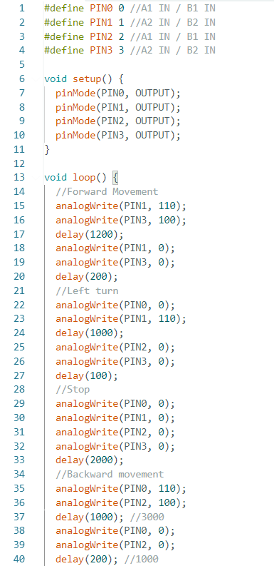
Considering that the motors can move at different speeds and are differently impacted by the surface friction, a calibration factor was implemented to the left motor's output pins. Particularly, through experimentation, I was able to determine that the calibration factor added to the left motor is 1.1 for the 2 meter line. Particularly, I observed a slightly increased speed of the right motor, which is why I experimented with decreasing the PWM signal which is sent to the right motor initially, and further experimented with the calibration factor once I had the car running in almost a straight line for the given distance. Therefore, I ultimately calculated the calibration coefficient of 1.1 applied to the left motor.
Considering the code above, I was able to achieve for my car to stay in the straight line by applying the delay of 200 in the section where the motors are powered off due to the pins PIN1 and PIN3 (which are directing the forward motion of the car) being set to 0.
Open Loop Demonstration
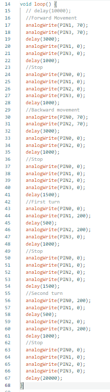
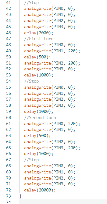
Following the calibration, our car is able to perform different movements through open loop control. In the demonstration attached below, the car moves forward, then turns to the left, moves backward and stops, and lastly spins both counterclockwise and clockwise (inspired by TA Mikayla Lahr's code).
The presented video was based on the code attached below.
Additional ECE 5160 Tasks
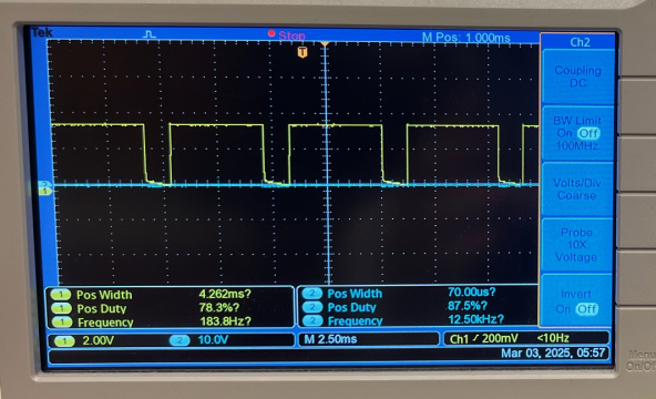
Frequency Analysis
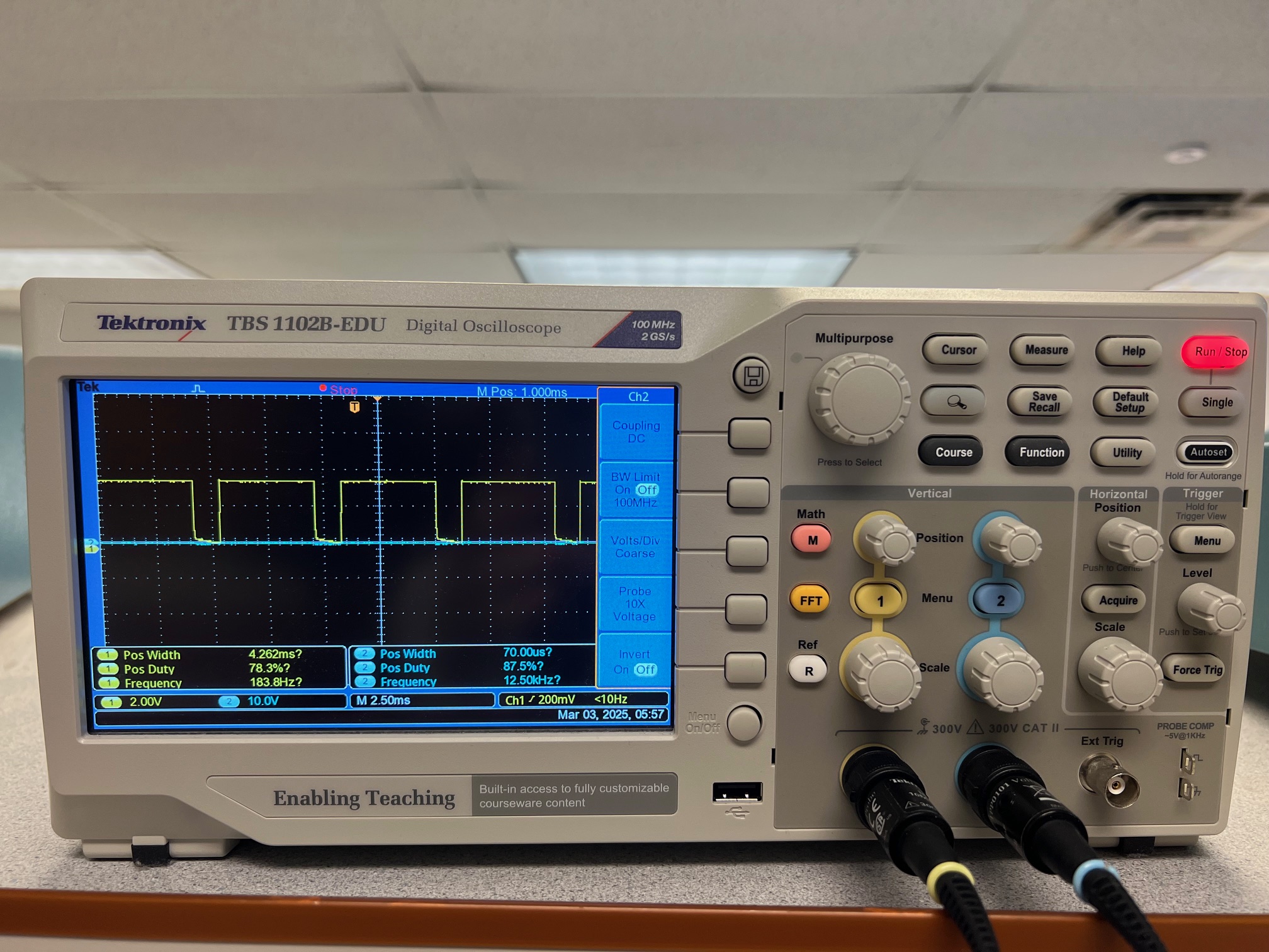
As the continuation to the performed oscilloscope testing, the PWM signal peak was estimated to occur at the frequency of which is equivalent to about 184 Hz. This corresponds to the frequency denoted on the attached image as well. Considering that the implemented motor drivers sample at about 50 kHz, which corresponds to 20 μs, the frequency that analogWrite() generates is fast enough for our motors to run analogWrite() tests and for ToF sensor data (considering the estimation from lab 2 about the sampling frequency). However, in theory, if we were to generate a faster PWM signal our motor driver could potentially make the car movements more controlled and streamlined. The code implemented for this part is attached below along with the complementary oscilloscope reading.
Lowest PWM Value Speed Discussion
The value obtained in the previous PWM task was 39 as the minimal value for the car to move forward. Hence, my thought process was to experiment with the values lower than 39 for all wheels, as that the car ought to already be in motion in this situation. Through repeating the process discussed in Lower Limit PWM Value Discussion section, I was able to manipulate the outputs values through Python in order for the car to already be in motion before determining the lowest PWM value. Hence, through experimentation, I was able to determine that the PWM value of 26 as the lowest PWM value when the car is already moving. With the duty cycle of ~101 (where 101 = ) would imply that we ought to have at least a car movement of 1.01 second as the initial motion of the car.
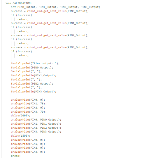
As can be inferred from the attached code snippet, the values are initially set to 78 for PIN1 and 70 for PIN3 as per the calibration factor, while other two pins are set to 0. After 2 seconds of being powered on to those values (as per the delay), values inserted through the Python ble.send_command() function are thus updated for another 2 seconds before all of the output pin values being set to 0. Due to the fact that the performed experimentation led to the lowest PWM value of 26, PIN1 and PIN3 are set to those values, as can be seen in the video below.
For comparison purposes, at PWM value of 25 set through Python, it was determined that the car cannot maintain the movement, and hence stops more quickly than in the previous video. This can also be confirmed by the number of tiles the car moved on in the video below.
Discussion
This lab was crucial in gaining a better understanding of our overall car system, as well as provided us with much more hardware debugging tasks compared to the previous tasks, which I found very enjoyable.
Debigging issue
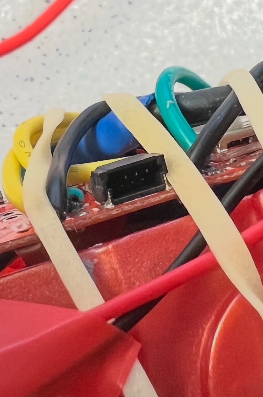
A unique issue that I encountered was the breaking of GND pin on the Artemis board's external connector. TA Harry was able to figure out the issue and help me with this, due to which a GND connection from the outside of the connector to the QWIIC connector was established. Images below show the missing pin of GND, as well as the new GND connection through a very thin blue wire from Artemis port to QWIIC connector port.
*This lab page is inspired by TA Mikayla Lahr's Lab 4 page from Spring 2024. Special thank you to TAs Harry Gao and Cheney Zhang for all their help with this lab!